1.Create Project
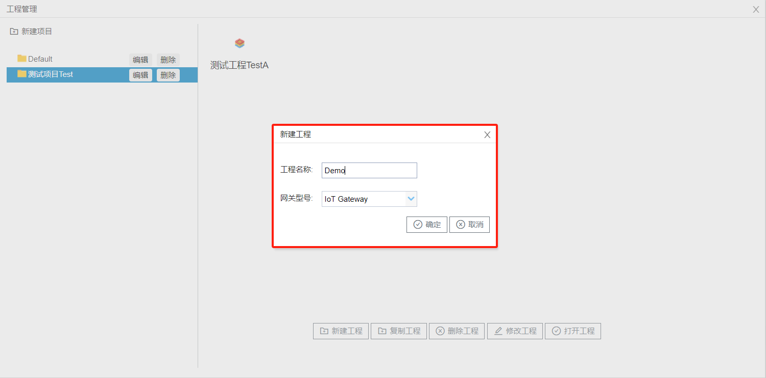
Open the configuration tool, click the Project Management button in the upper-left corner, select the corresponding project, then click Create New Project. In the pop-up Create New Project dialog box, enter a project name (e.g., "demo" as shown here), select your gateway model, and click OK. See the figure below.
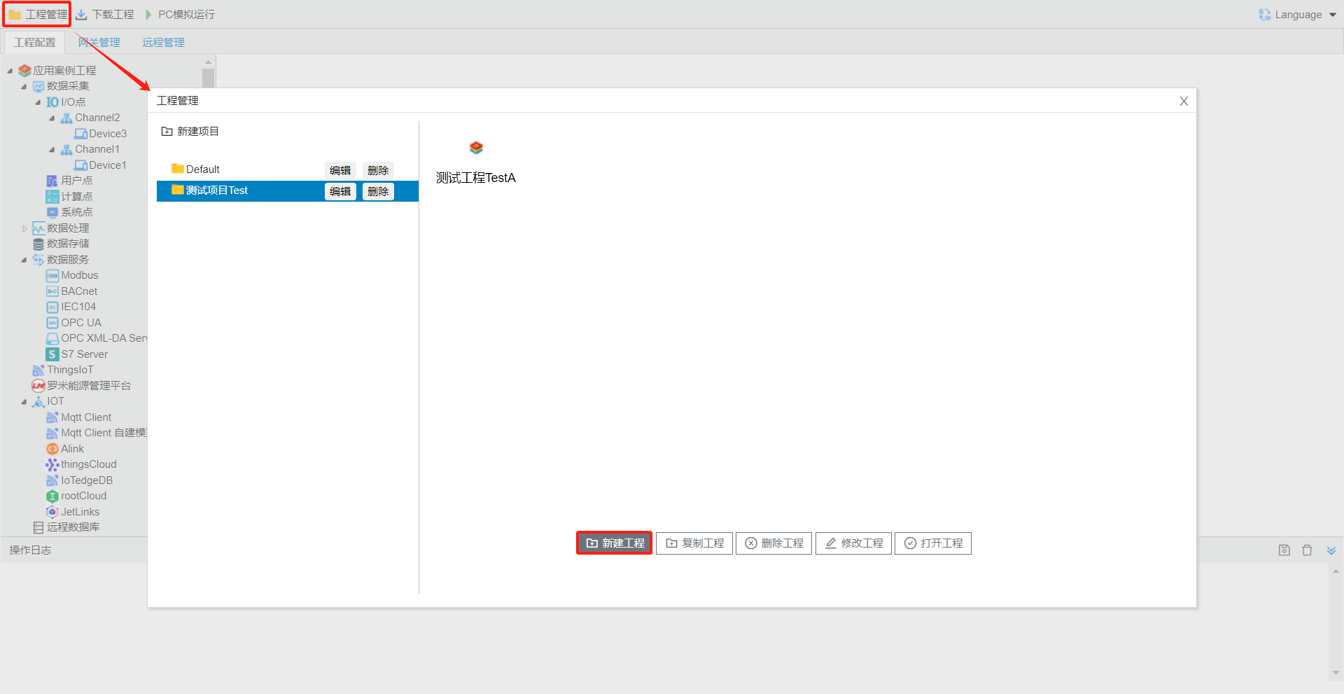
At this point, the configuration tool will display all contents contained in this project directly within the navigation menu bar, with the root node labeled using your project name. All subsequent project configurations will be performed under this root node.
For detailed step-by-step instructions on creating a new project, please refer to----2.2 gatewayproject Management
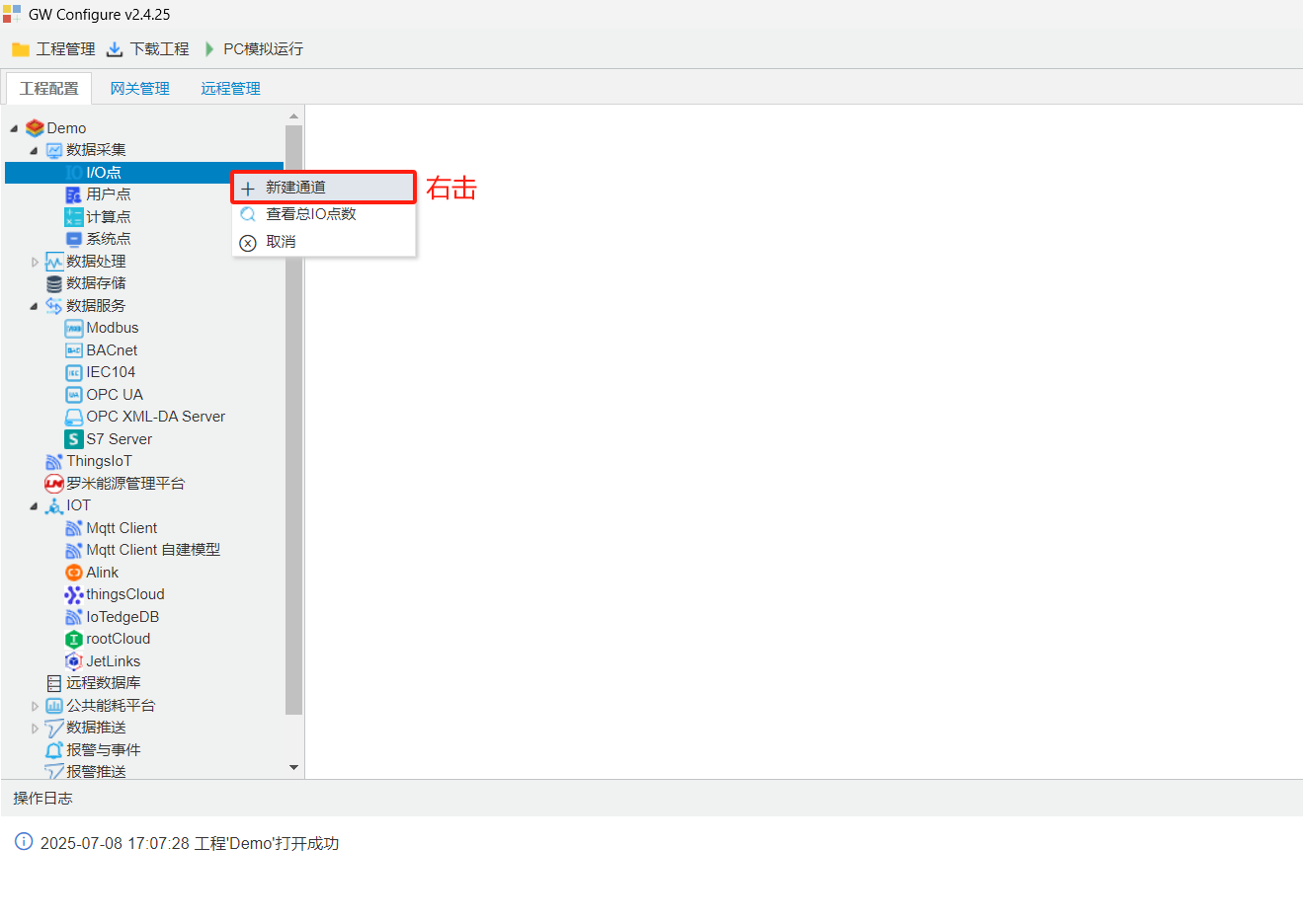
2. Create Channel
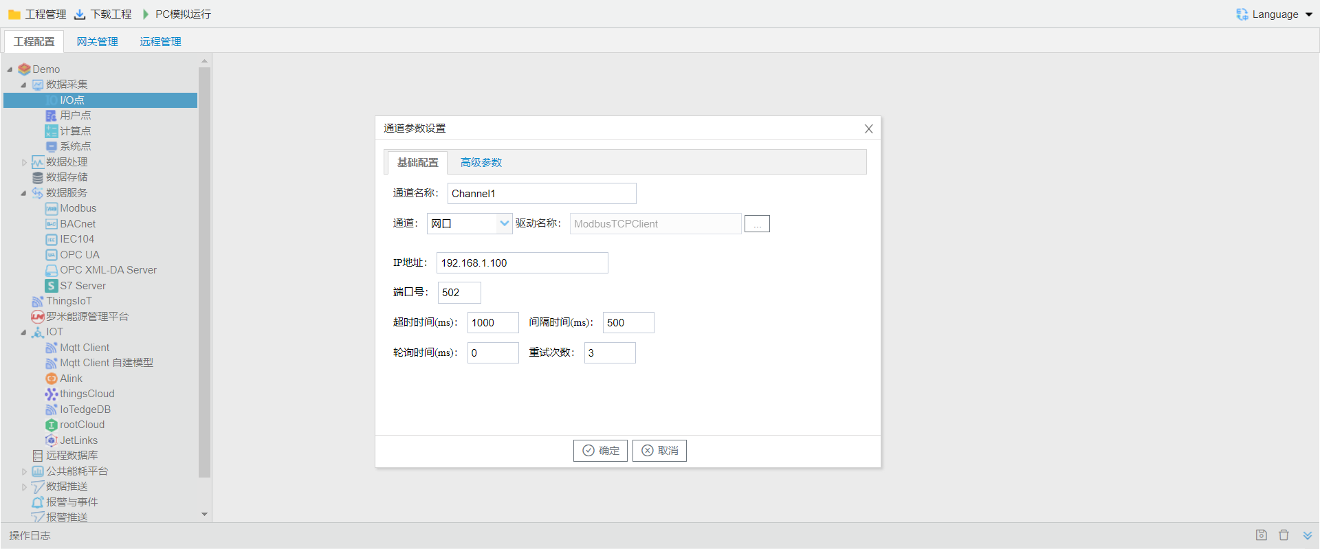
Right-click the I/O Points tab and select Create New Channel. Enter a channel name, choose the channel type (Serial Port / Ethernet Port), then pick the acquisition driver type. For demonstration purposes, we will select the ModbusTCP Client protocol here.
**For other channel parameters, please refer to **createchannel. such as.
3. Create Device
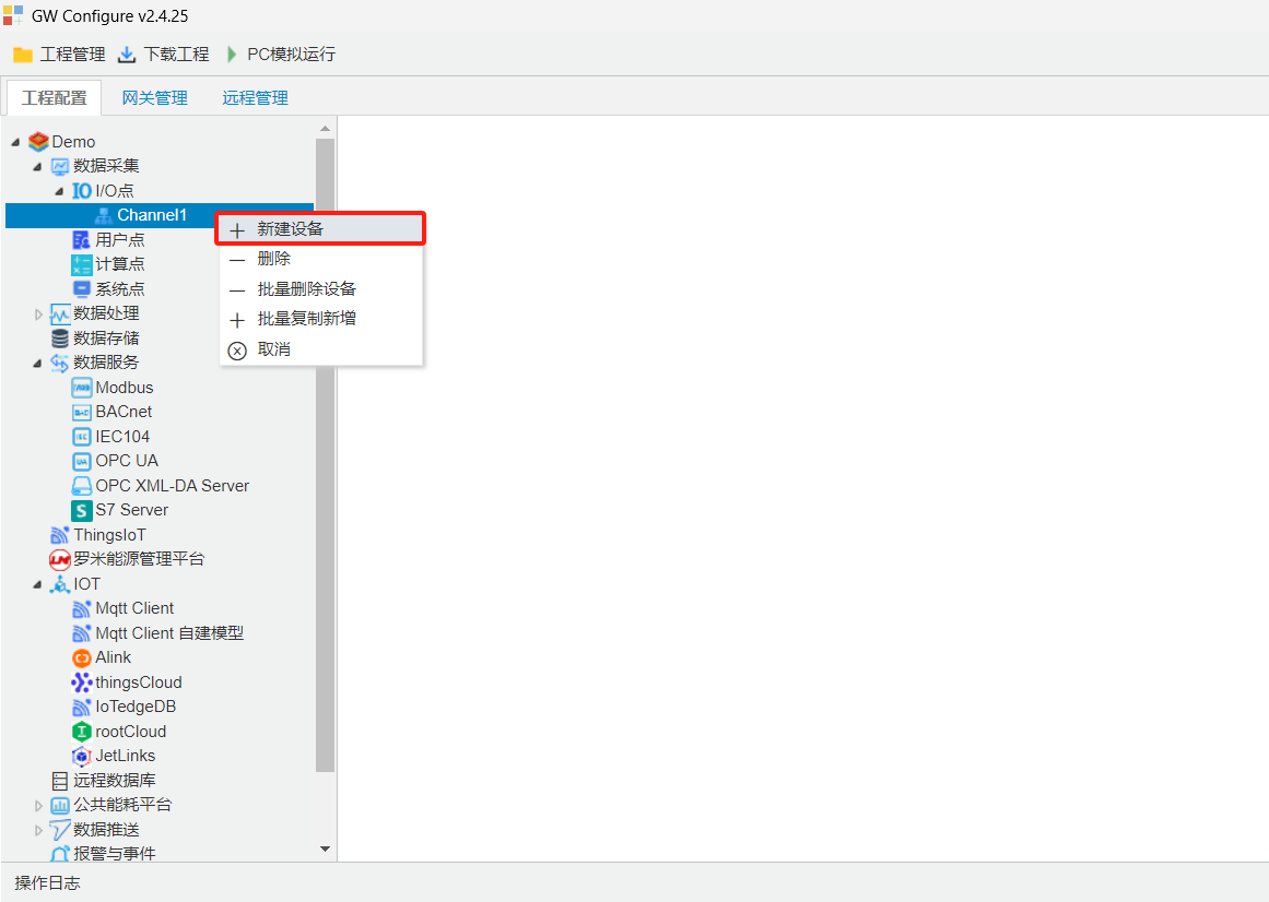
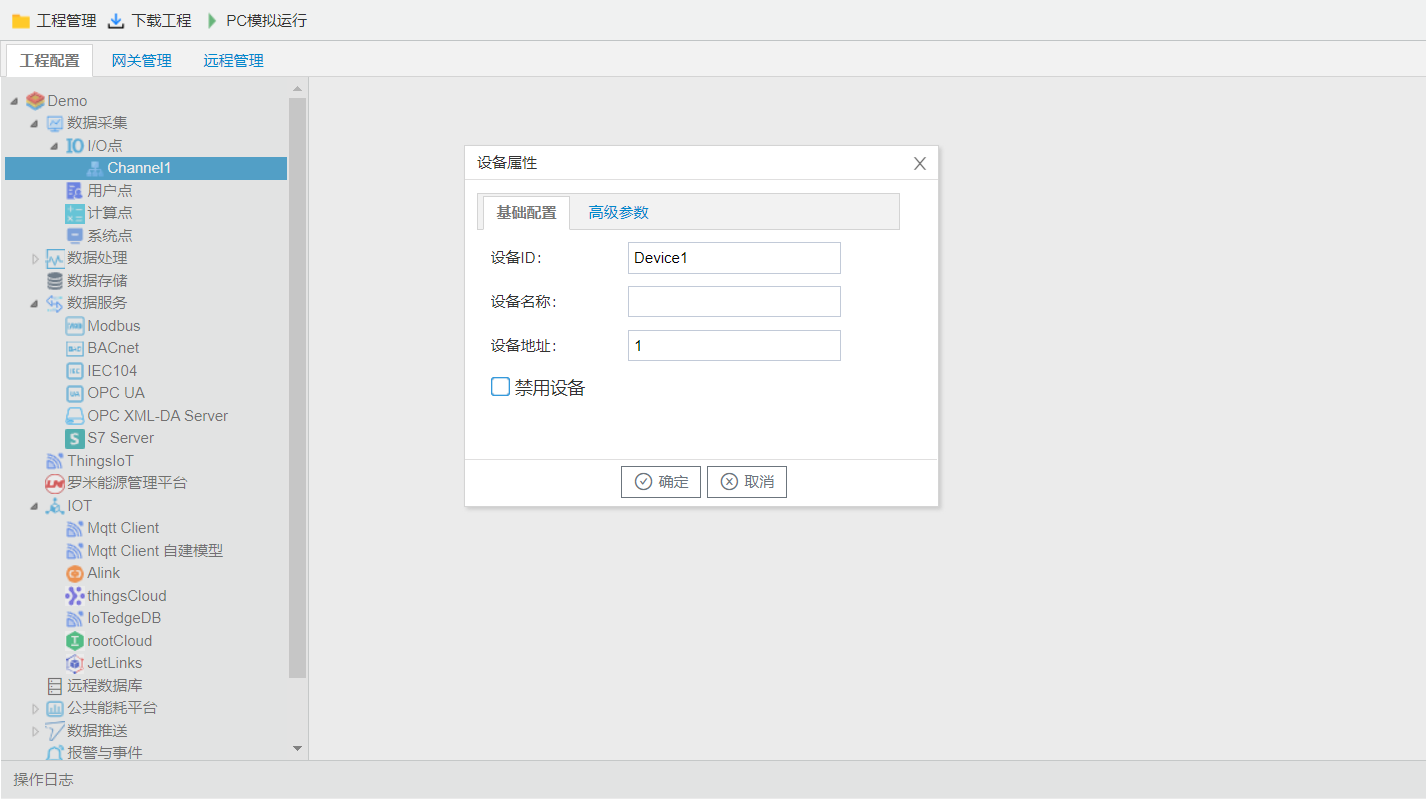
Select the newly created channel, right-click and choose Add New Device. Enter the device name and device address.Device Parameterseecreatedevice. See the figure below.
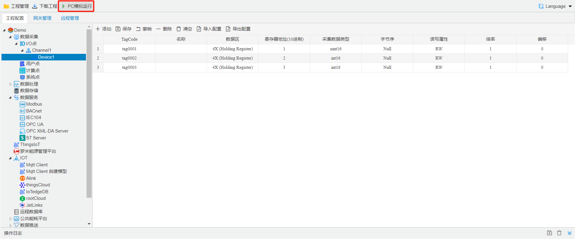
4. Config Data Acquisition Point
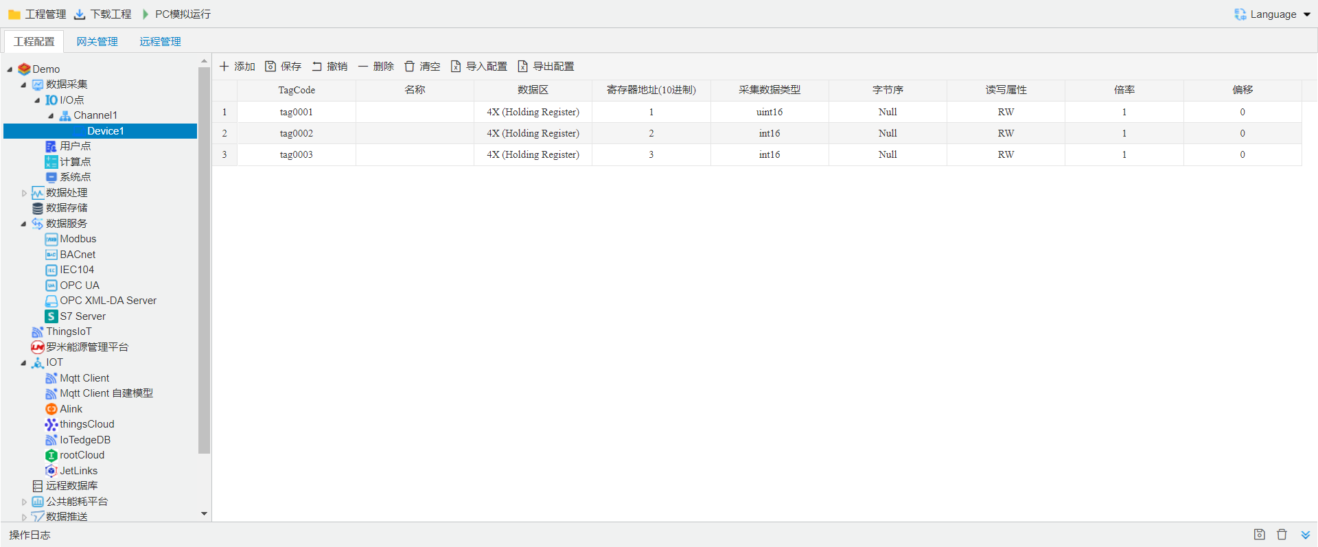
Click to select the device where you need to create new data points. All configured data points under this device will appear on the right panel, where you can add, delete or edit entries directly in the table.
You may export the current configuration as an Excel file via the Export Config button, make adjustments in Excel, then import the file back into the configuration tool using Import Config.
For proper data point setup, select the protocol driver matching your on-site hardware.
Other Data Acquisition Driver refer to LM acquisition protocol
5. Data Services
Click to select Modbus under the Data Services menu, then configure the Modbus service on the page that pops up on the right.
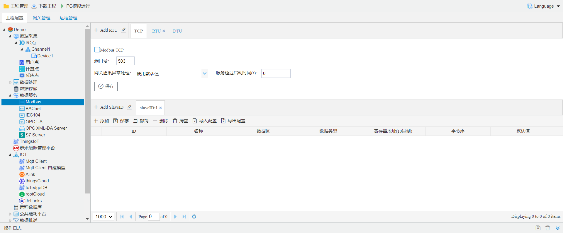
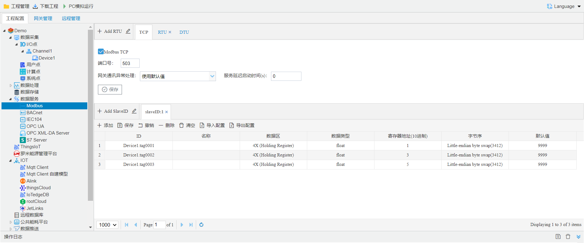
The top section of the Modbus service page contains protocol settings for the Modbus service, while the bottom section lists data points mapped to this service, including mapped data areas, register addresses, data types, and byte order.
This example is for a Modbus service. When configuring other data services, the configuration approach remains the same: you need to first configure the protocol settings, and then perform data point mapping (including the data points to be uploaded, the addresses to which they are mapped, etc.). Plz refer to 3.4 Data Services
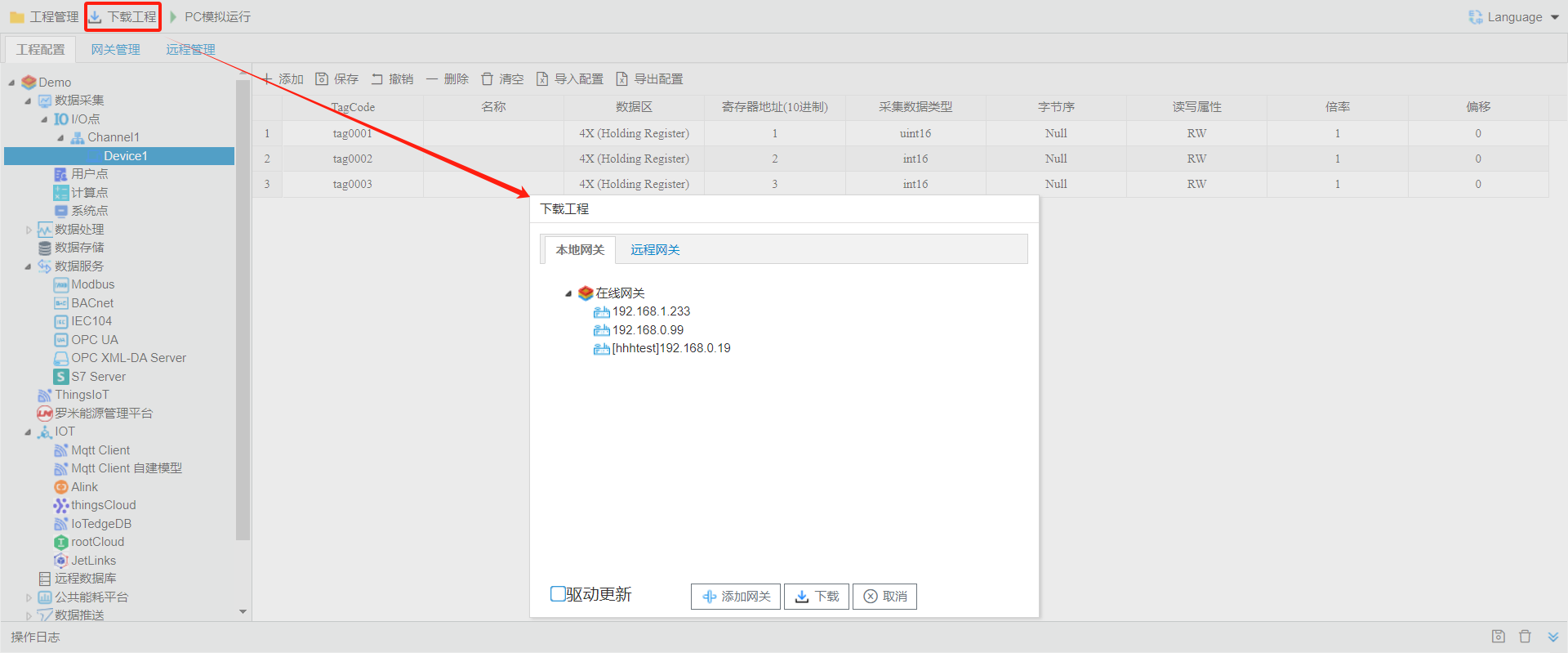
6. Download Project
Download the current project to the specified gateway so that the gateway runs with the current project configuration.
Click Download Project, then select the gateway and click Download to finish the process. For full details, please refer to 6.2 downloadproject
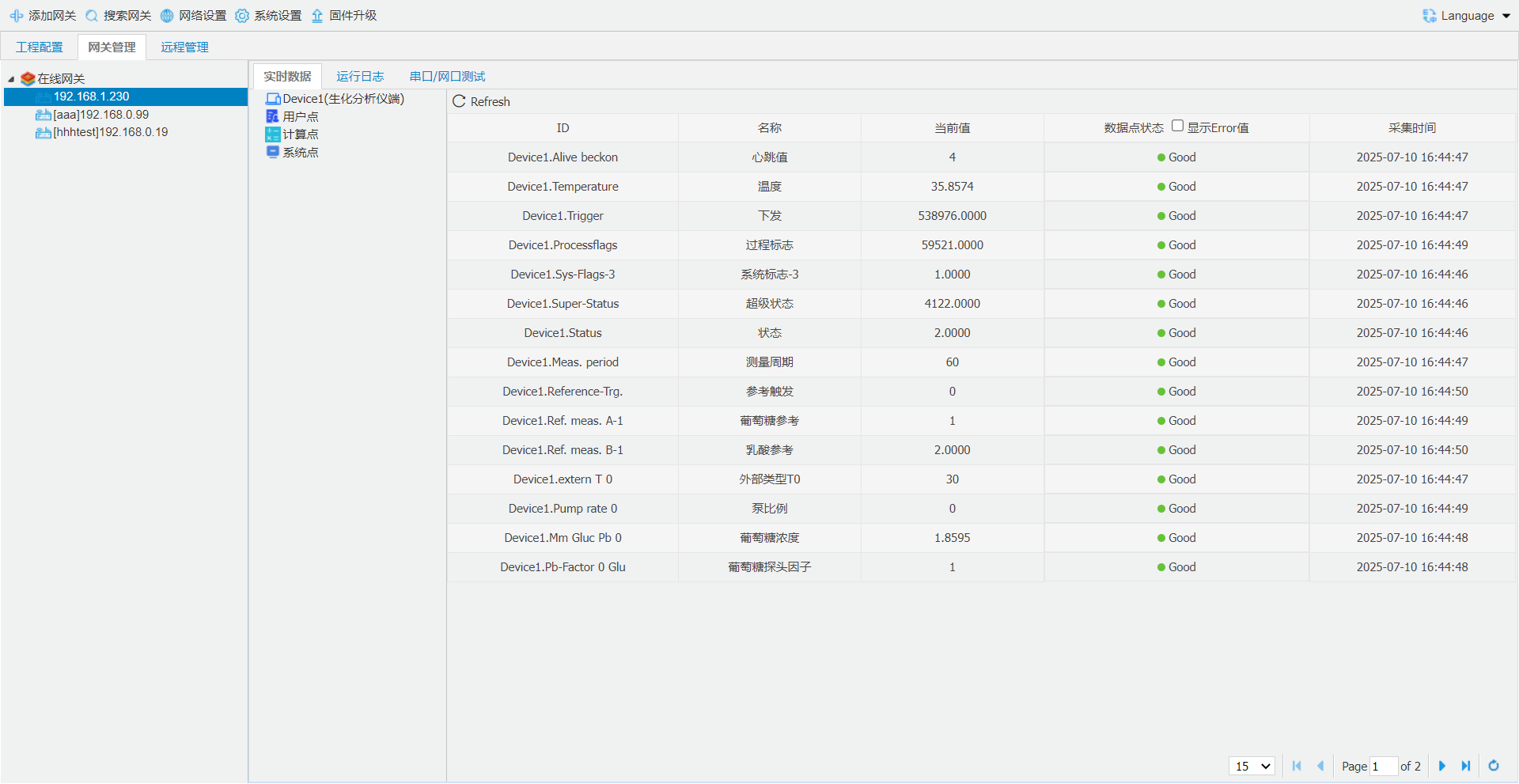
7. View Real-Time Data
After downloading the project to the gateway, view the gateway's real-time data in the Gateway Management section. Select the target gateway to access real-time data, as well as operational logs and serial/Ethernet port debugging.
8. PC Simulation
Run the current project on the PC, using the PC's serial port and network port for data acquisition and data services. The system log window will display the logs and messages output during program runtime, allowing users to debug the project in the PC environment. For details, please refer to 6.1 PC Simulation Run