Quick Start
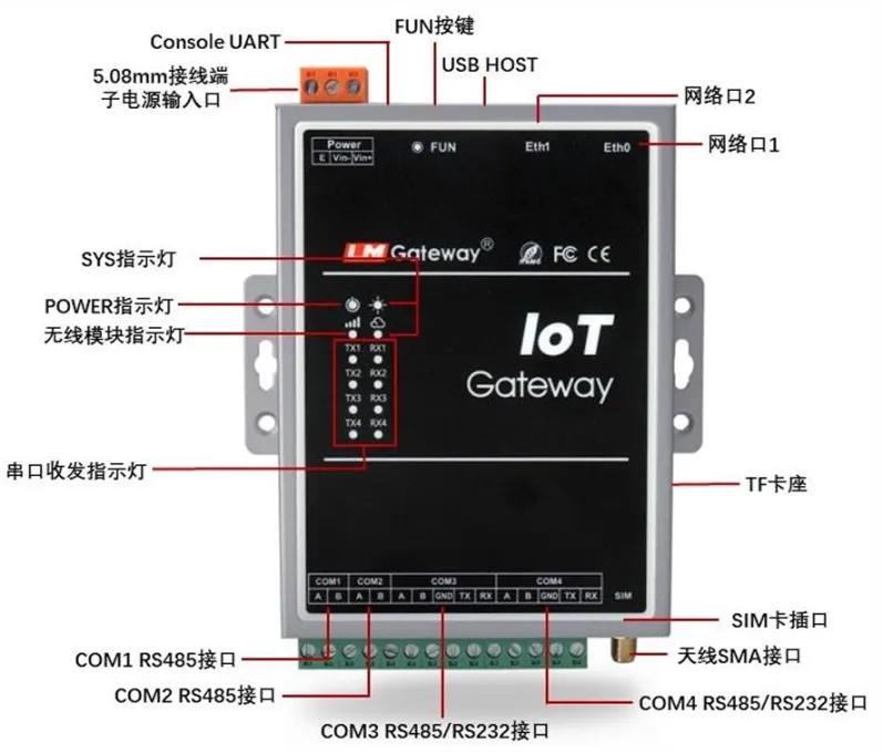
1. Gateway Interface Overview
After receiving the gateway, customers usually need to perform debugging and configuration. The following section uses the LM Gateway403-IoT gateway model as an example to describe the detailed configuration process.
For an introduction to other gateway models, please refer to IoT Gateway - LM Measurement & Control.
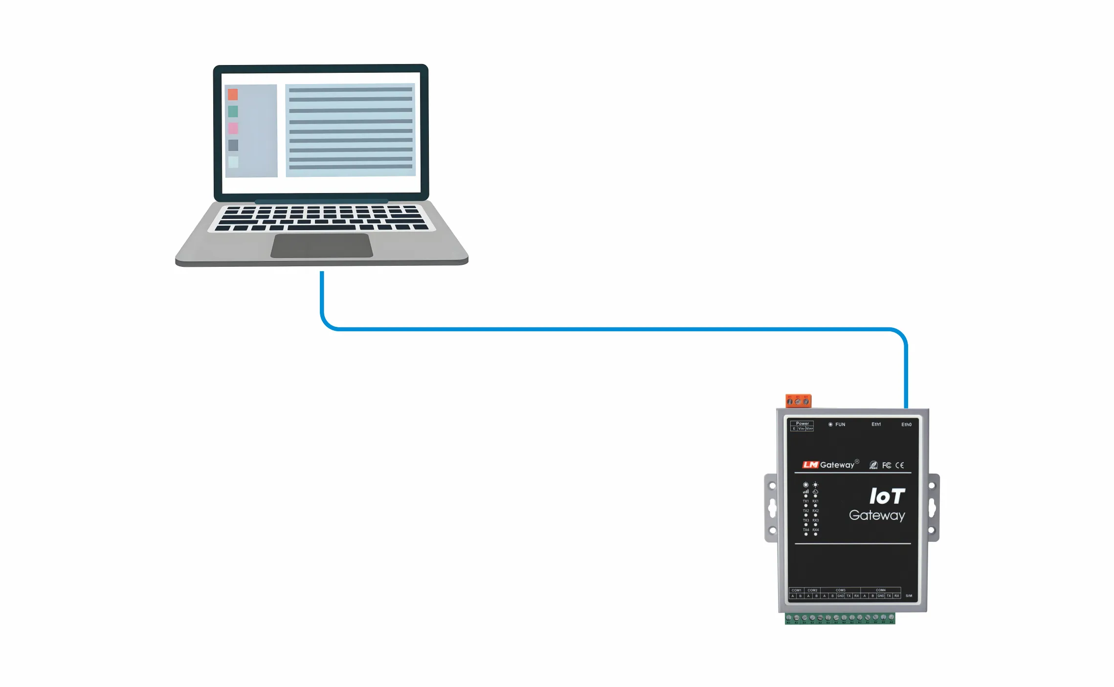
2. Connect the Computer to the Gateway
2.1 Connect the Gateway and Computer with an Ethernet Cable
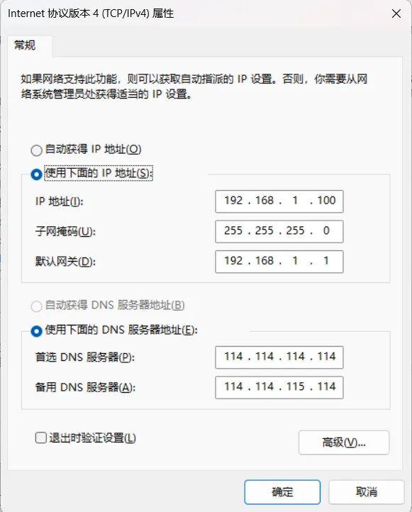
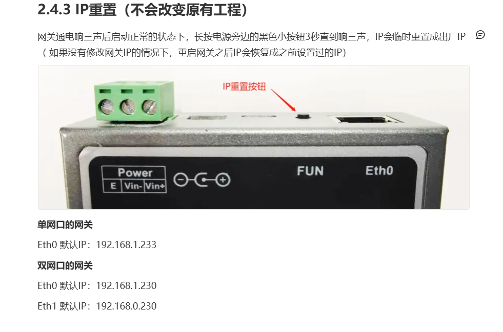
2.2 Configure the Computer IP Address (Keep the Computer and Gateway on the Same Network Segment)
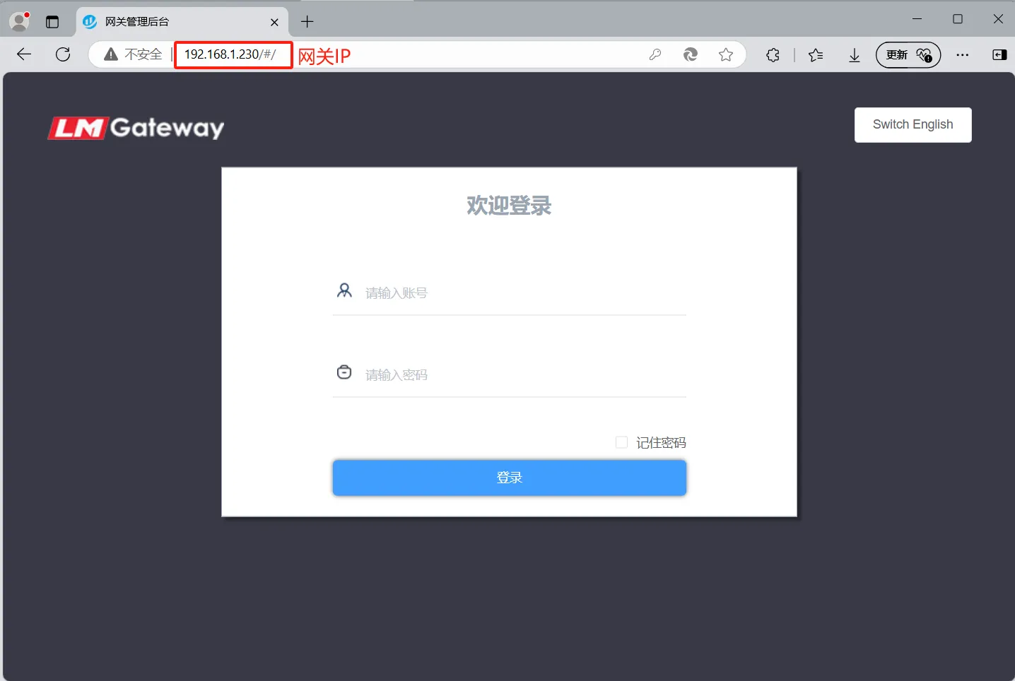
2.3 Access the Gateway Web Page from a Browser
If the gateway web page can be accessed normally from the browser, the gateway and computer are connected properly.
Browser Login (Username/Password: admin/admin)
3. Configure the Gateway Project
Configure the gateway project to collect data from on-site devices and instruments, and provide the required data forwarding services.
3.1 Open the Configuration Tool
Download link LM Gateway Configuration Tool V2.4 Download
Run the configuration tool from the software installation directory.
Note 1: The configuration tool installation directory should not contain Chinese characters, spaces, or special characters .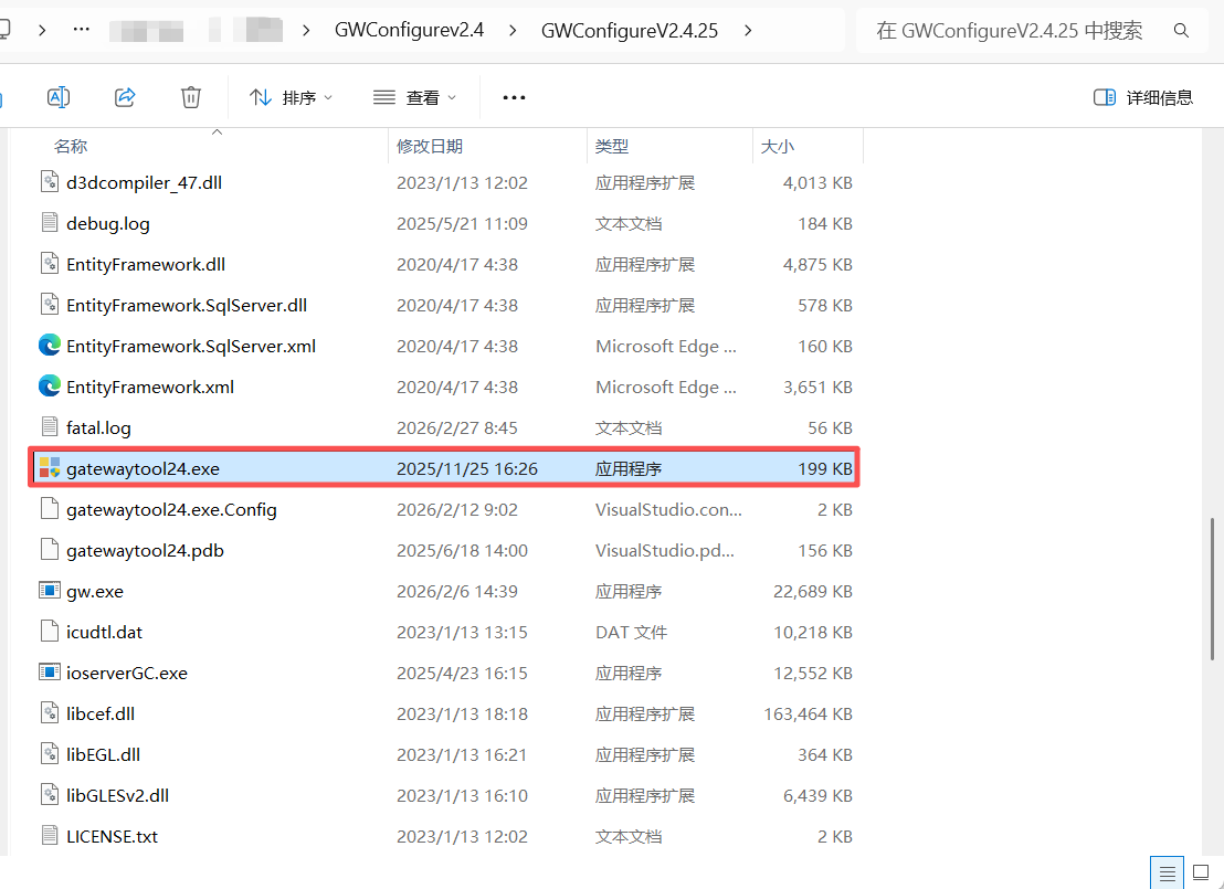
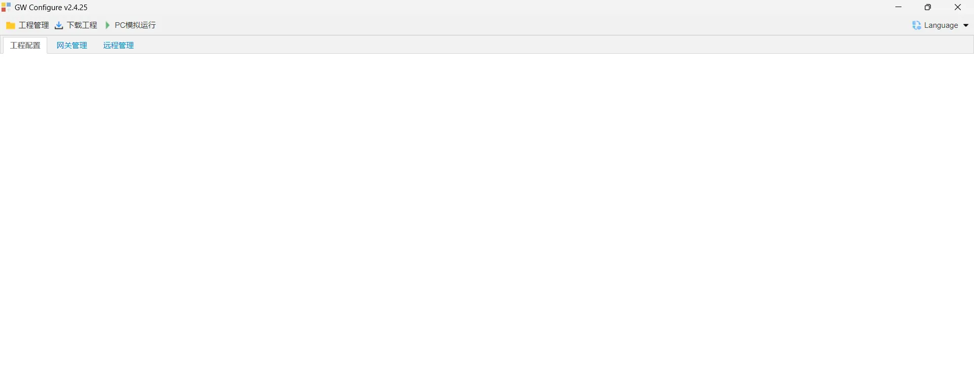
3.2 Project Management
For more details, refer to: Gateway Project Configuration
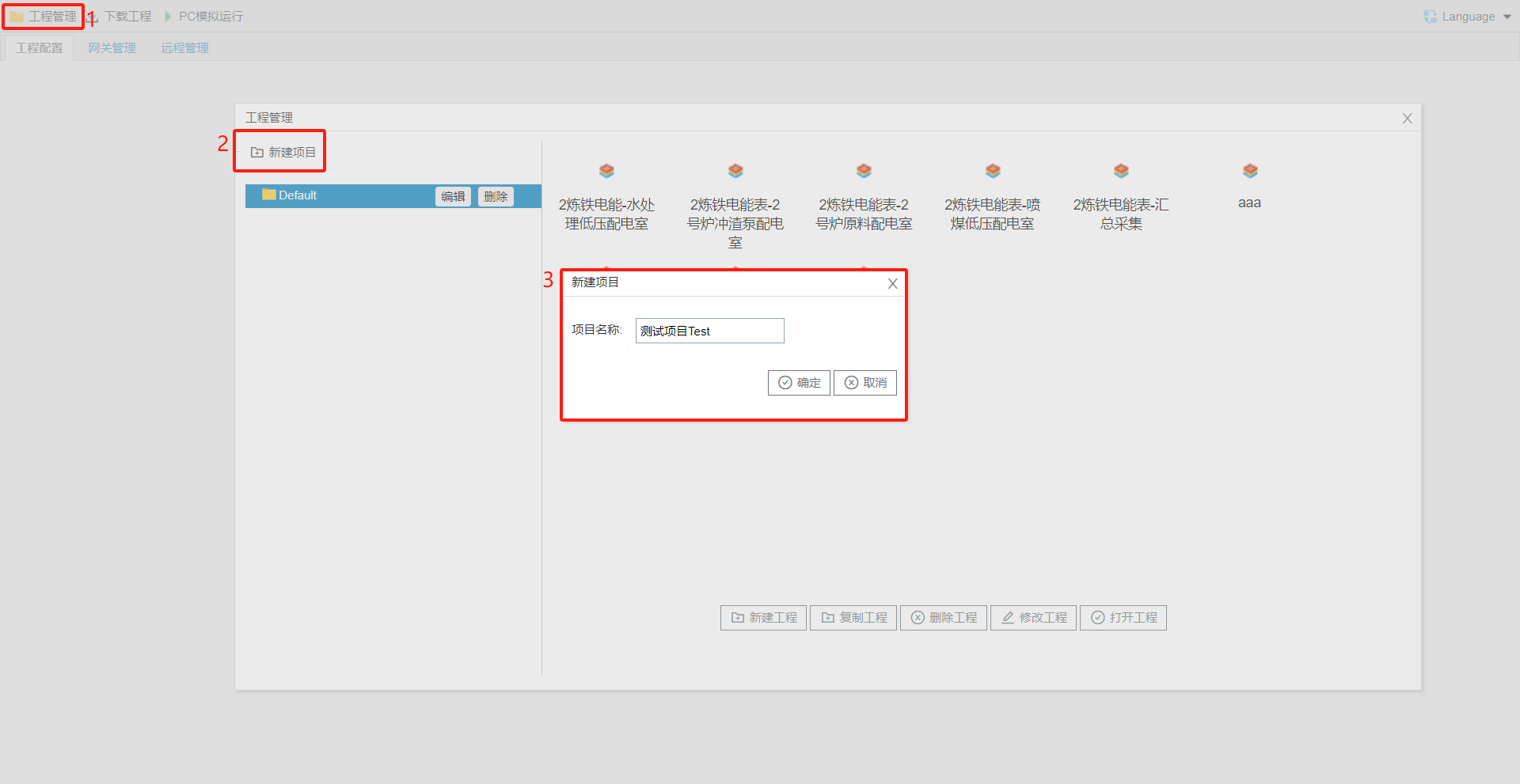
Create a New Project
Click Project Management ----> New Project ----> Edit the project name ----> Click OK to create the project
3.3 Project Data Acquisition Configuration
For more details, refer to: Create a New Channel
Based on the data transmission protocol provided by the on-site devices and instruments, the gateway configuration tool is used to configure the device data acquisition function.
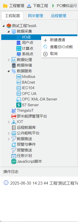
Create a New Channel
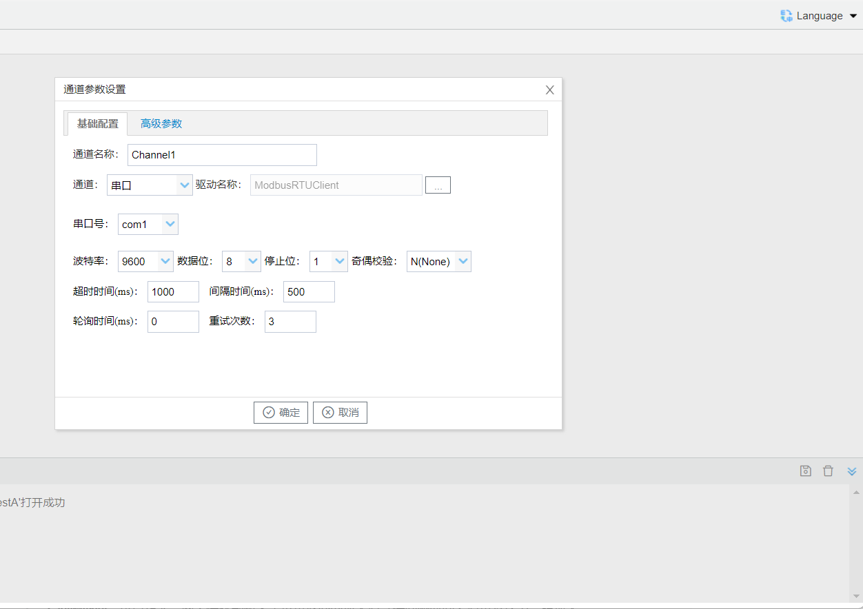
Right-click "I/O Points" and select New Channel. The channel parameter settings window will pop up. Select the channel, driver, and other parameters according to the actual devices to be acquired.
warning
For configuration of other acquisition protocols, refer to the link below.
LM Acquisition Protocol Summary
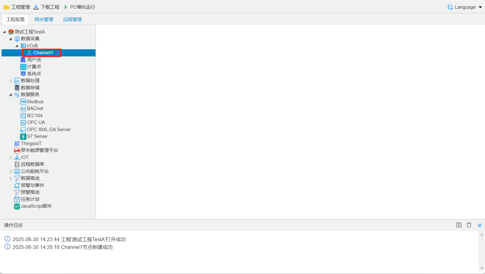
New channel created successfully
Create a New Device
For more details, refer to: Create a New Device
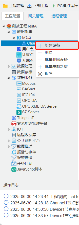
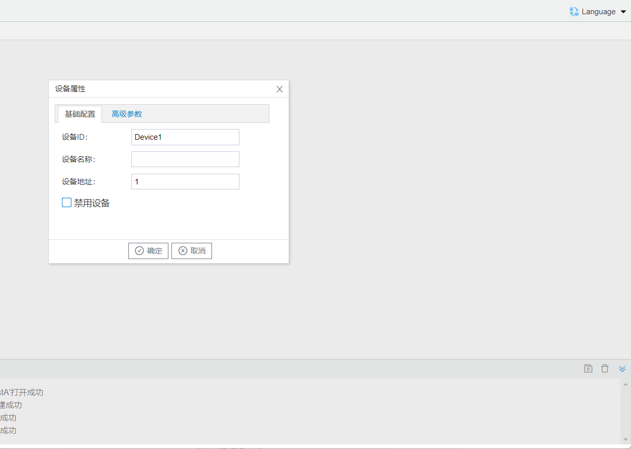
Right-click "Channel (Channel1)" and select New Device. The device properties window will pop up. Enter the device ID and device address according to the actual device to be acquired.
Add Data Points
For more details, refer to: Data Point Acquisition Management
Left-click the device for which data points need to be created. The edited data points under that device will be displayed on the right side, where you can add, delete, or modify entries in the table. You can use “ Export Configuration ” and “ Import Configuration ” to export the current configuration as an Excel file. After completing the configuration in Excel, import it back into the configuration tool.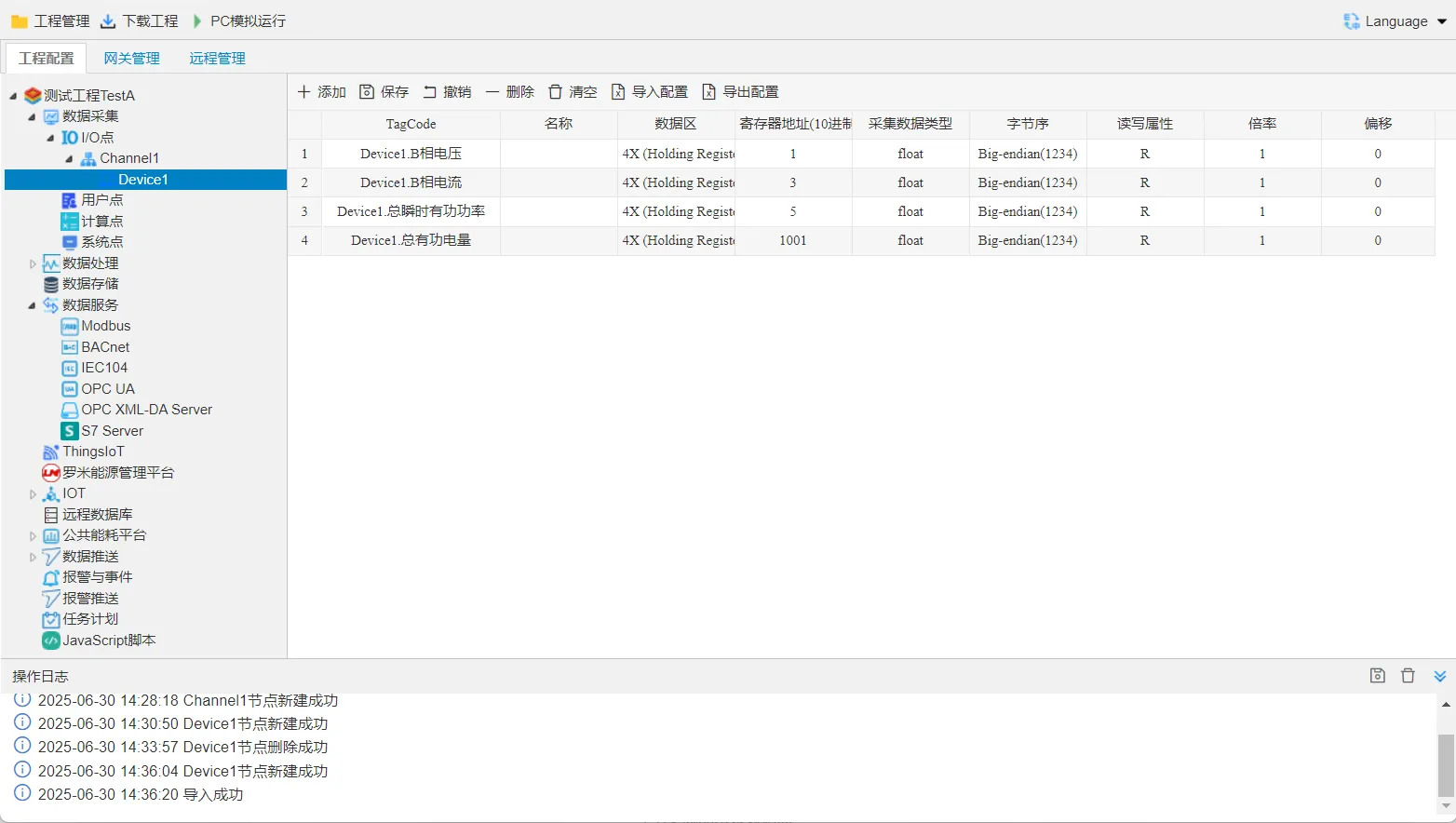
3.4 Project Data Forwarding Service Configuration
For more details, refer to: Data Service
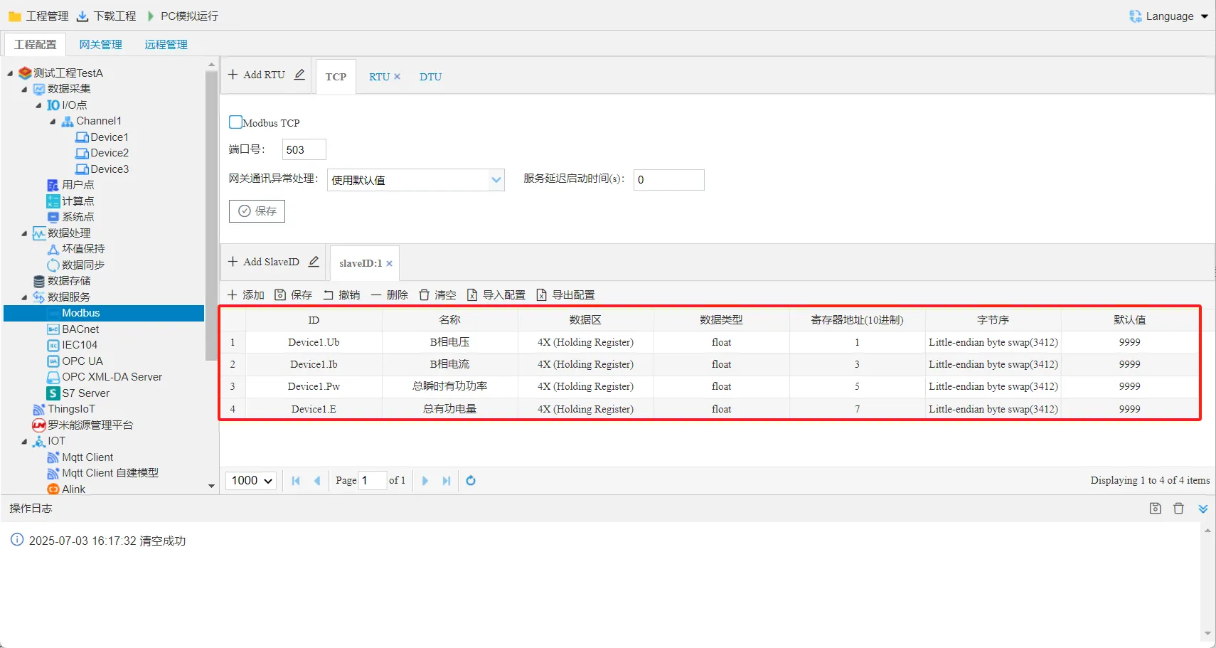
Example: The Modbus server maps Tag points to Modbus registers, allowing a host computer that supports Modbus Client to read and write Tag points through Modbus TCP or Modbus RTU. It also supports multiple slave IDs and allows multiple services to be added.Configure the gateway data forwarding services according to customer requirements, such as Modbus service, BACnet service, OPC service, and so on.
Select Enable Modbus TCP Service, then click Save.
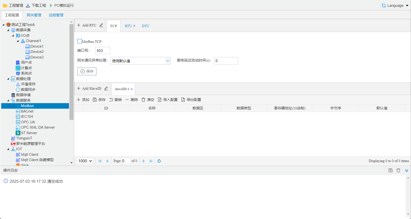
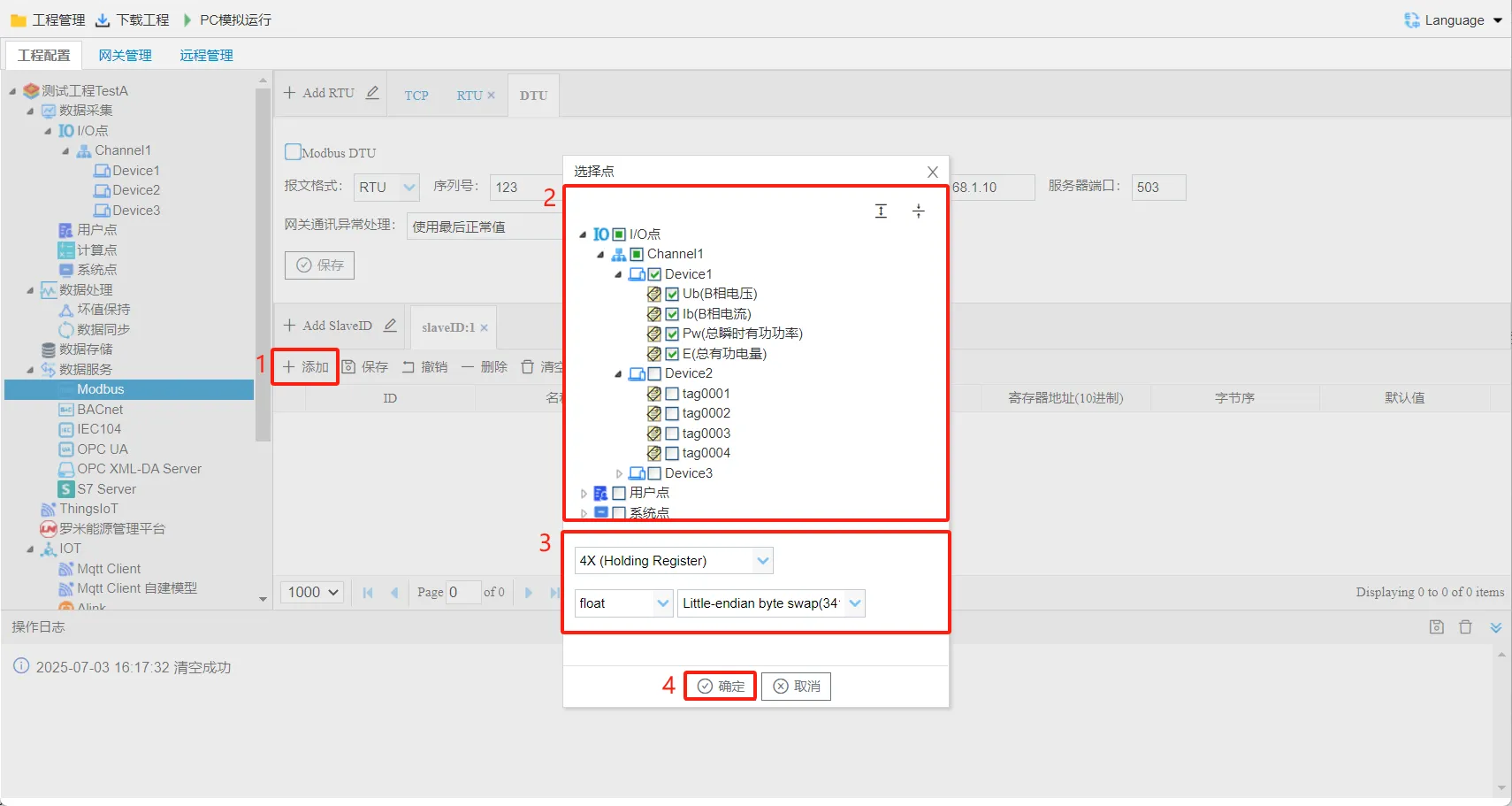
Modbus Address Mapping
Map Tag points to Modbus registers. The configuration steps are as follows:Repeat the above operations to add more points to the address list.
- Click the “Add” button.
- In the pop-up window, select the points to be mapped.
- Select the Modbus data area, data type, and byte order.
- Click the “OK” button to finish adding the mapped points.
4. Download the Project
For more details, refer to: Download Project
After the gateway project configuration is complete, the project must be downloaded to the gateway before it takes effect.
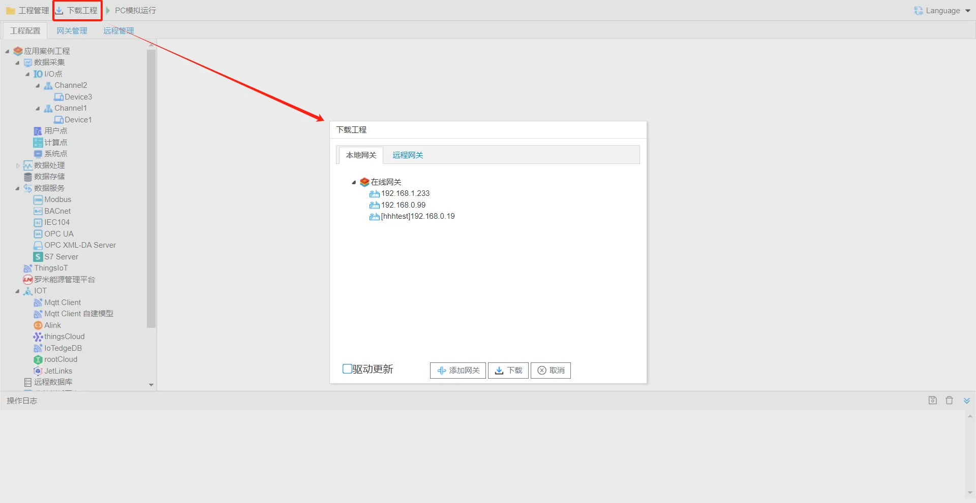
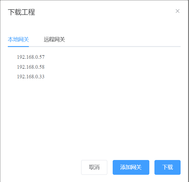
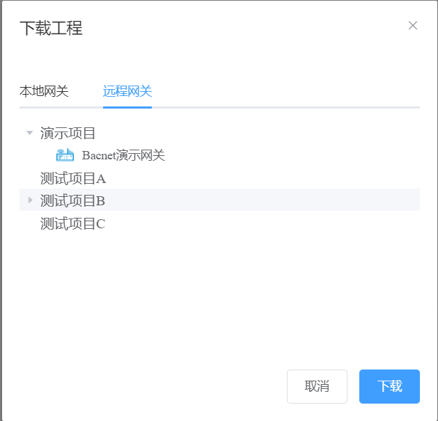
Click Download Project to open the pop-up window. Two modes are supported: local LAN download and remote download. Select the gateway and click Download. The project will be downloaded to the specified gateway.
Local Download: The gateway and computer are on the same LAN. You can also manually add a gateway by entering its IP address (click Add Gateway).
Remote Download: The remote gateway must be a gateway added under the same account on the thingsIoT page.
5. Gateway Management
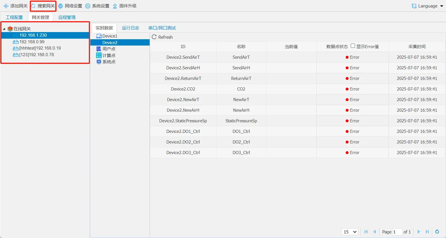
After the project is downloaded to the gateway and the acquisition devices are properly connected to the gateway, you can monitor the real-time data collected by the gateway on the gateway management page.
Search for Local Gateways
For more details, refer to: Search Gateway
You can use the configuration tool to search for online gateways on the LAN.
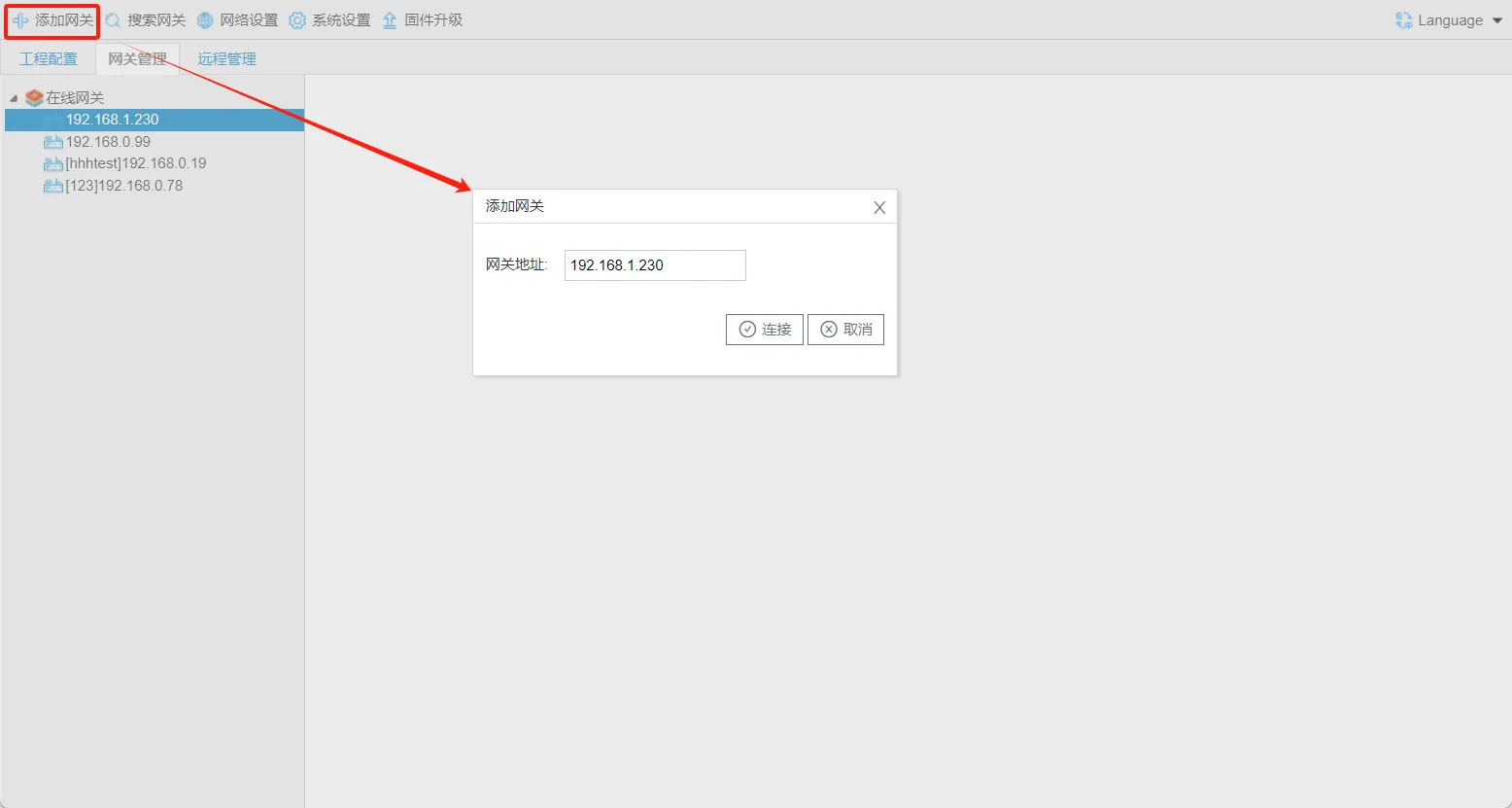
Add Gateway
Click Add Gateway to manually add a gateway on a different network segment within the LAN.
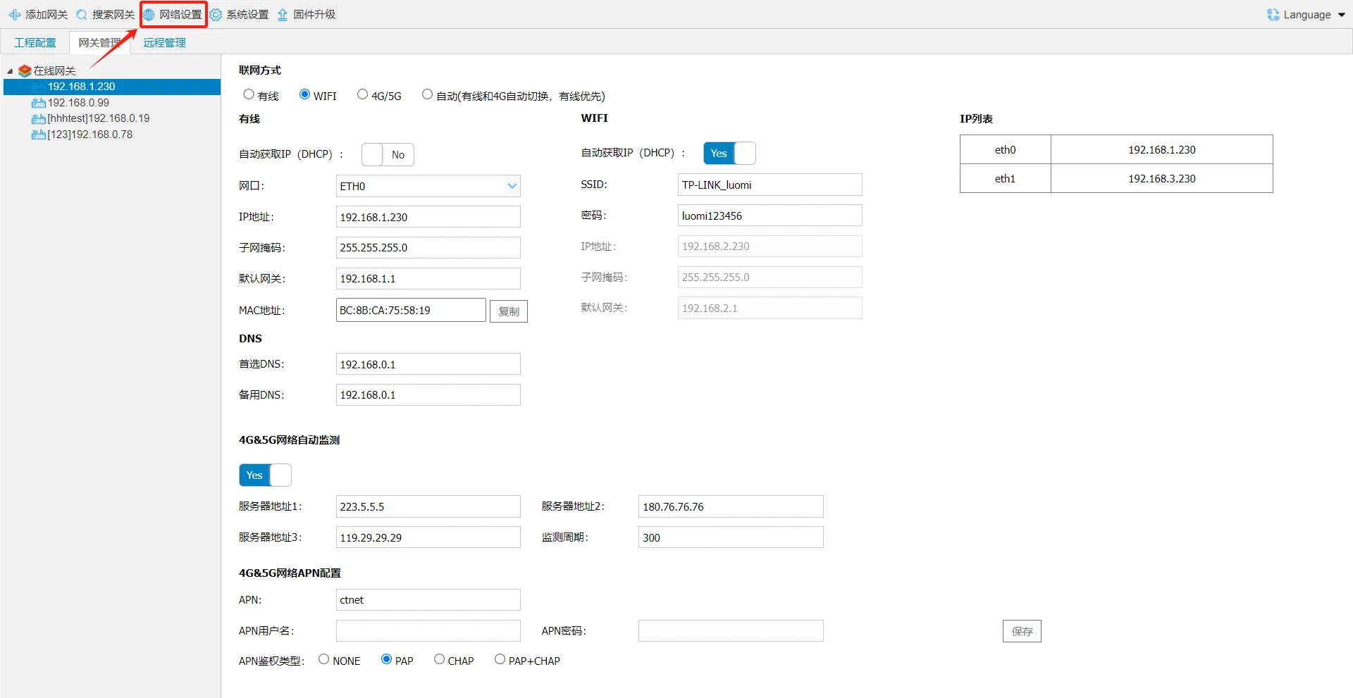
Network Settings
For more details, refer to: Network Settings
Select a gateway and click [Network Settings] to open the gateway network settings page.
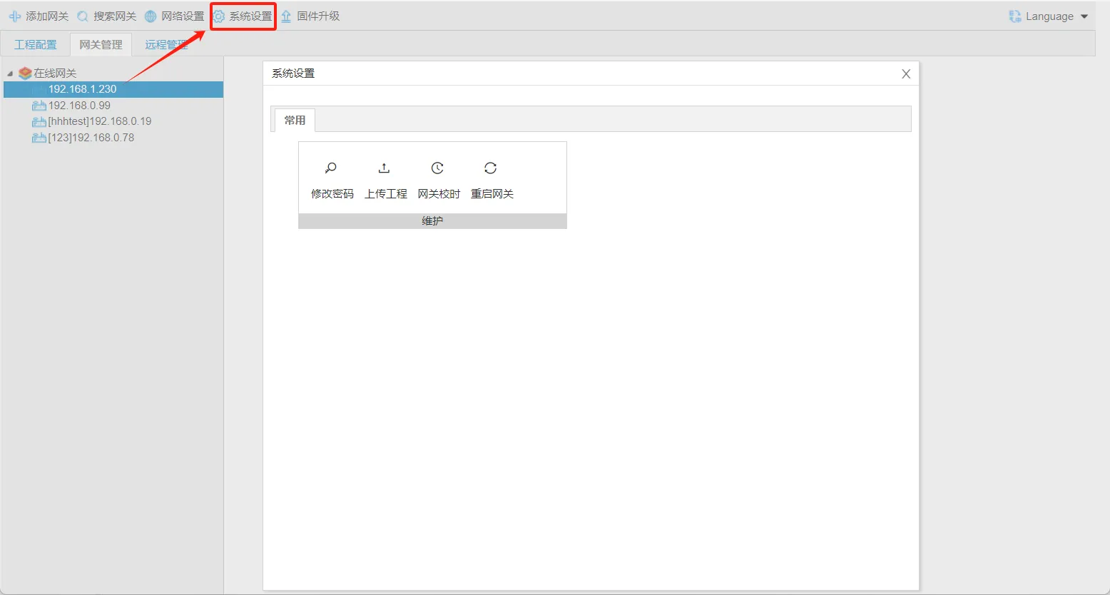
System Settings
For more details, refer to: System Settings
Select a gateway and click [System Settings] to open the gateway system settings page.
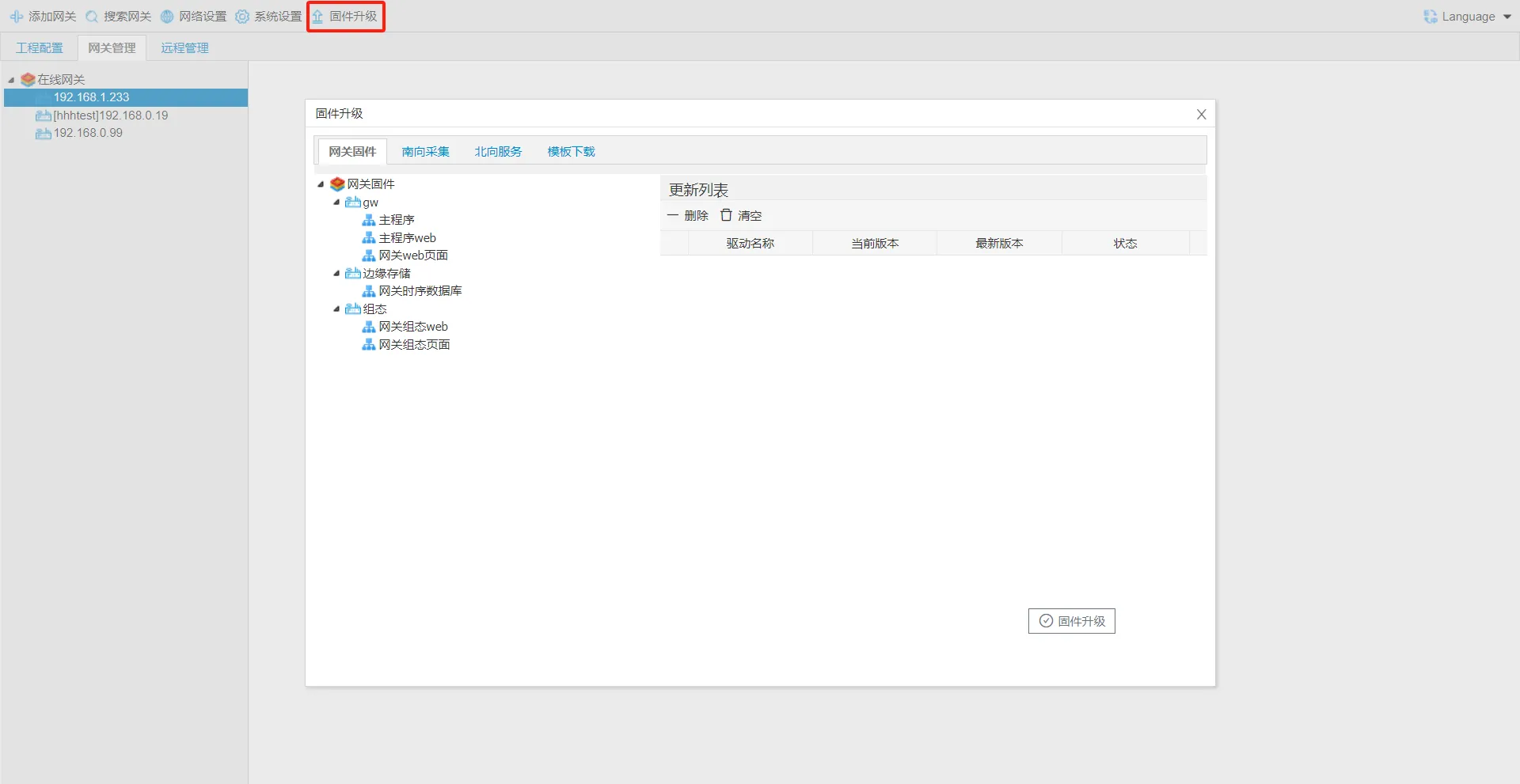
Firmware Upgrade
For more details, refer to: Firmware Upgrade
Click Firmware Upgrade to open the upgrade page. You can download and upgrade the gateway firmware, data acquisition drivers, data services, and JS templates.
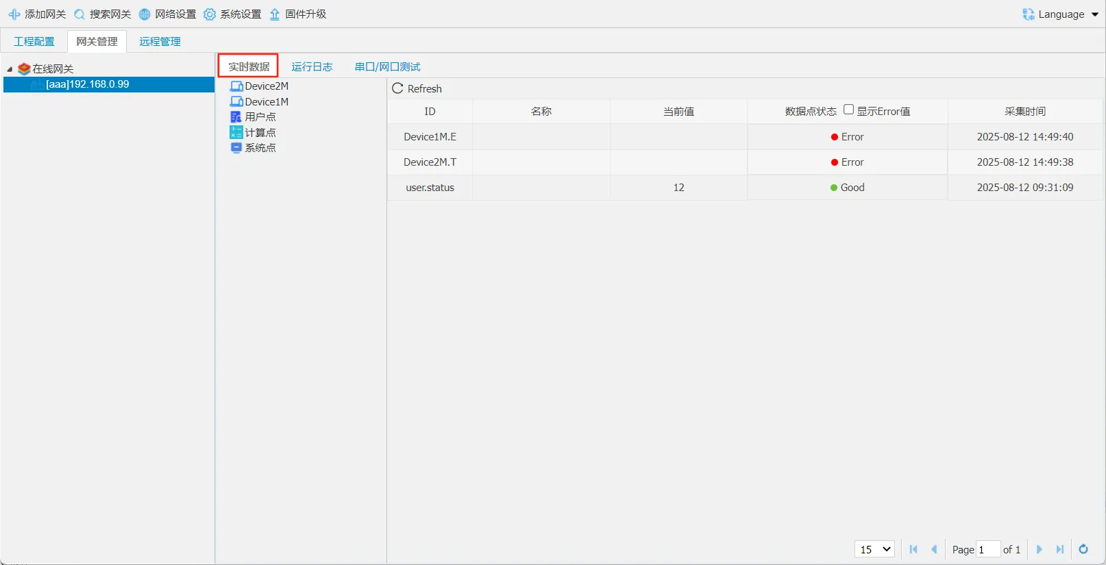
Gateway Real-time Data
For more details, refer to: Real-time Data
After entering the gateway, view the gateway data on the [Real-time Data] page. The data includes acquired data, user point data, calculated point data, and system point data.